Unloader valve ALS Mk-3 air brake system : construction and working
The unloader valve ALS Mk-3 is a basic and important parts of the air brake system. The unloader valve ALS Mk-3 is also works as a safety device of the air brake system. So now we learn about the unloader valve ALS Mk-3 that what is the construction and working of the unloader valve ALS Mk-3.
Construction of the unloader valve ALS Mk-3 :-
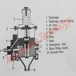
The unloader valve ALS Mk-3 have one air inlet from air compressor and one air outlet to the air brake system. The unloader valve ALS Mk-3 also have a extra socket for air outlet for filling air into the spare tyre.
Unloader valve ALS Mk-3
The unloader valve ALS Mk-3 have a gauge type filter inside its body for clean entire air before going to the system. There is a NRV (non return valve) is also fitted at the outlet of the unloader valve ALS Mk-3. This NRV valve prevent the system's air from back flowing it means it not allow to back flow the air from the system.
There is a governor plunger and a rubber diaphragm is also provide inside the unloader valve ALS Mk-3 body for remaining a desire pressure on the unloader valve ALS Mk-3. The unloader valve ALS Mk-3 is fitted inside the body and also a spring is fitted along with it to keep it in initial position.
There is a continuity channel also casted inside the unloader valve ALS Mk-3 body. The function of this continuity channel is describe into the working of unloader valve ALS Mk-3 as below.
Working of unloader valve ALS Mk-3 :-
After vehicle starting the air compressor unit gets drive from the engine timing gears and starts working and sends the compressed air to the unloader valve.
Now the incoming air enter into the unloader valve ALS Mk-3 body and clean by the gauge filter. After cleaning the air flow to the system. This process remains continues till the system pressure reached at 8.5 kg/cm2.
After reaching the pressure at 8.5 kg/cm2 the same pressure trying to flow back and closed the NRV valve and same pressure is act ont the rubber diaphragm through the continuity channel and the rubber diaphragm moves upward.
The rubber diaphragm is remains connected with the governor plunger so the governor plunger is also moves upward now there is a minner clearance happen between governor plunger and unloader valve.
So from this clearance the system's 8.5kg/cm2 pressure also pull the unloader valve to downward and the spring of the unloader valve will close. For downward moving of the unloader valve the atmospheric way will open and connected with air inlet.
Now the incoming air directly release into the atmosphere while the system's air pressure till not come below 8.5kg/cm2.
Now supposed the driver used the system's air then the system's air pressure is comes below 8.5kg/cm2. Then the rubber diaphragm and governor plunger moves downward and close the air way which make a pressure on the head of the unloader valve.
Because the above reason the unloader valve also move upward and close the atmospheric way. Now the incoming air is again start to goes to the system.


.webp)
.webp)

0 Comments